
The Response Meter tool is designed for measuring response times. Of course, for a one-time measurement, it's sufficient to read the appropriate timestamp from the log, but in situations where we need to perform multiple measurements, for example, to capture a situation where the response is not sent on time, searching through the log becomes complicated. In such cases, this tool is appropriate to use.
This tool offers several variants of response time measurement:
- Measuring the time between two messages on the CAN bus, thus measuring on a functional system where 2 messages occur: request and response. We want to measure the time between these messages.
- Measuring the time between two messages, the first of which (request) is generated by the PP2CAN program, and we want to precisely measure the arrival of the response.
- Measuring the time between sending a message on CAN and activating the Marker input of the USB2CAN Triple/Combo converter. For example, we connect the Marker input to the digital output of a device to which we send a command to switch this output. This measures how long it takes for the switching to occur.
- The opposite situation, measuring the time between activating the Marker input and a CAN message. That is, how long it takes from the activation of the device input (and the parallelly connected Marker input) until a message is generated on the CAN bus.
In case we use a CAN message sent from the PP2CAN program as a request (the second case), it is appropriate to use firmware series 3.XX for the USB2CAN converter. This firmware with the Back Sender function sends back to the PC the actual time (timestamp) of sending the message on the CAN bus. The measurement is thus not affected by processing time in queues in the PC, USB latency, etc., which is in the order of at least milliseconds (Windows scheduler, etc.).
Now several measurement examples:
 |
 |
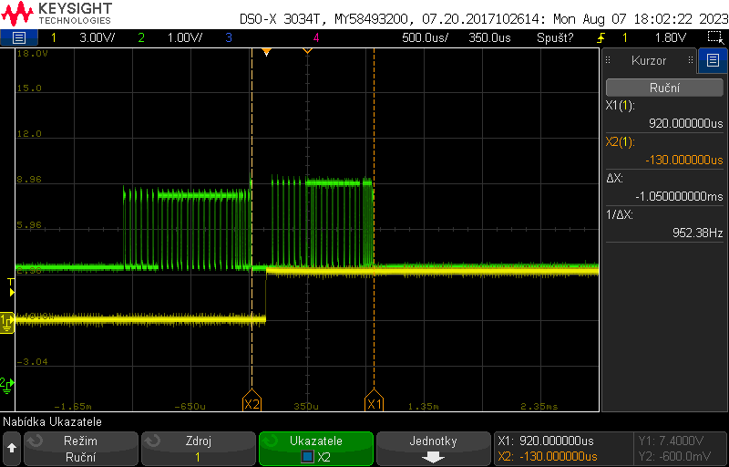
| In this case, we are measuring the response to a command to activate a digital output. That is, the distance between the end of the message when it is delivered to the device and how long it takes for the output to respond by switching. The request is set to this message, TX mode is set, because the message is sent from the PP2CAN program and not captured from the CAN bus where it would be sent by another device. The Response message has the Marker option checked. In this case, the response is the activation of this digital input of the USB2CAN Triple converter. We see the value of 116 μS in the Response meter tool and in the oscilloscope screenshot (deltaX). | |
 |
 |
| A similar situation to the previous one, but we changed the Response option to falling edge (Falling edge)... | |
 |
 |
| In this case, we are measuring how long it takes from receiving a command to activate an output until a confirmation message is sent on the CAN bus (end of message). The device on which we were performing measurements confirms the activation of the output with a message. Both Request and Response are CAN messages, and we are not using the Marker input. We are still sending the request from the PP2CAN program, which is why the TX option is active. | |
 |
 |
| We are measuring the distance between two messages running on CAN 2. The logging option is also set if the response (second message) arrives later than 1300μS. In the case of the first such event, the PP2CAN program logging is also stopped so that the log can be analyzed at this point and, for example, a delay in the response can be detected due to an overly congested CAN bus. | |
If you need to measure the period of a message and detect its outages, you can use the Timing Accuracy tool.